
 English
 Suomi
 Norsk bokmål
 Svenska
 Lietuvių kalba
 Latviešu valoda
 Polski
 Русский
 Deutsch
 Eesti
 Nederlands
Less spin. Better fuel efficiency.
When less power is lost to track spin on slippery surfaces, fuel use may fall. The benefit depends on the surface, snowmobile setup and riding style.
iGrip ST & SS · Installation guide
Choose and install iGrip ST & SS studs.
Match your snowmobile track model, lug height and prepared holes to the right screw-in studs. Find quantities, drilling dimensions and installation patterns for a wide range of track variants.
Find my track ↓
01 / START HERE
Choose your track and lug height, then select the model code to see its stud quantities and dimensions. Variants with factory-prepared holes have their own fitting instructions.
Check the location of your tunnel protectors. Our patterns are recommendations: do not install studs directly beneath the tunnel protectors. We recommend fitting tunnel protectors.
Select a track above to see its studs, drilling dimensions, diagrams and quantities.
YOUR TRACK GUIDE
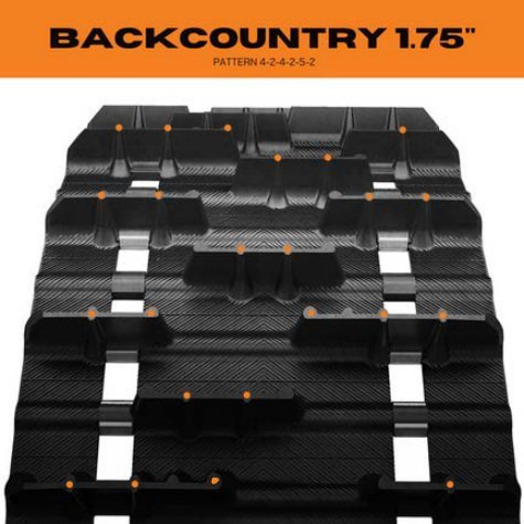
| Model | Length | Width | Lug height | Pitch | Rows | Studs (pcs.) |
|---|---|---|---|---|---|---|
| 9140C | 121″ (3 073.4 mm) | 15″ (381 mm) | 1.75″ (44.45 mm) | 2.52″ (64.01 mm) | 48 | 152 |
| 9141C | 128″ (3 251.2 mm) | 15″ (381 mm) | 1.75″ (44.45 mm) | 2.52″ (64.01 mm) | 51 | 162 |
| 9142C | 136″ (3 454.4 mm) | 15″ (381 mm) | 1.75″ (44.45 mm) | 2.52″ (64.01 mm) | 54 | 171 |
| 9143C | 144″ (3 657.6 mm) | 15″ (381 mm) | 1.75″ (44.45 mm) | 2.52″ (64.01 mm) | 57 | 181 |
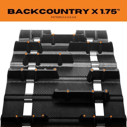
| Model | Length | Width | Lug height | Pitch | Rows | Studs (pcs.) |
|---|---|---|---|---|---|---|
| 9254C | 141″ (3 581.4 mm) | 15″ (381 mm) | 1.75″ (44.45 mm) | 3″ (76.2 mm) | 47 | 180 |
| 9287C | 120″ (3 048 mm) | 15″ (381 mm) | 1.75″ (44.45 mm) | 2.86″ (72.64 mm) | 42 | 161 |
| 9288C | 129″ (3 276.6 mm) | 15″ (381 mm) | 1.75″ (44.45 mm) | 2.86″ (72.64 mm) | 45 | 172 |
| 9289C | 137″ (3 479.8 mm) | 15″ (381 mm) | 1.75″ (44.45 mm) | 2.86″ (72.64 mm) | 48 | 184 |
| 9328C | 153″ (3 886.2 mm) | 15″ (381 mm) | 1.75″ (44.45 mm) | 3″ (76.2 mm) | 51 | 195 |
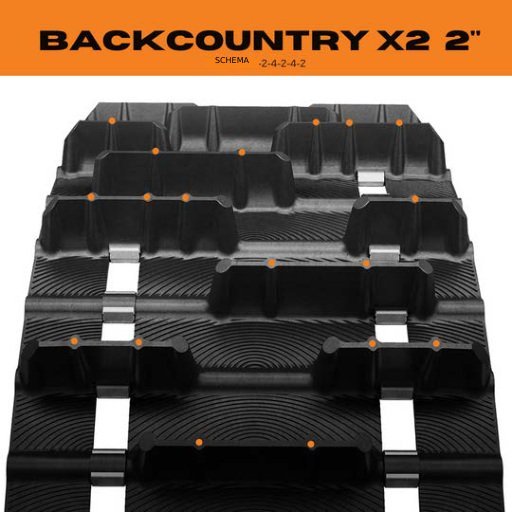
| Model | Length | Width | Lug height | Pitch | Rows | Studs (pcs.) |
|---|---|---|---|---|---|---|
| 9258C | 137″ (3 479.8 mm) | 15″ (381 mm) | 2″ (50.8 mm) | 2.86″ (72.64 mm) | 48 | 144 |
| 9417C | 146″ (3 708.4 mm) | 15″ (381 mm) | 2″ (50.8 mm) | 2.86″ (72.64 mm) | 51 | 153 |
Dimensions are shown in inches and millimetres.
YOUR TRACK GUIDE
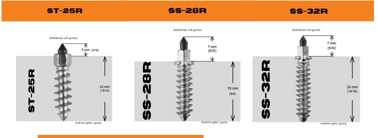
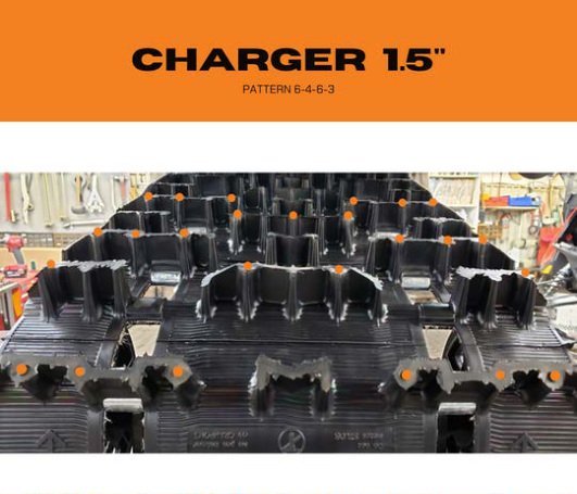
| Model | Length | Width | Lug height | Pitch | Rows | Studs (pcs.) |
|---|---|---|---|---|---|---|
| CHARGER | 154″ (3 911.6 mm) | 16″ (406.4 mm) | 1.5″ (38.1 mm) | 2.86″ (72.64 mm) | 54 | 198 |
Dimensions are shown in inches and millimetres.
YOUR TRACK GUIDE
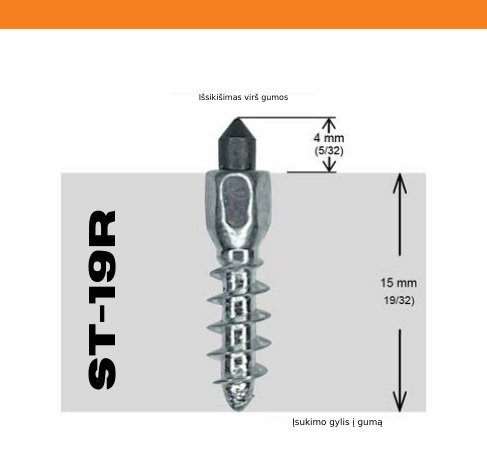
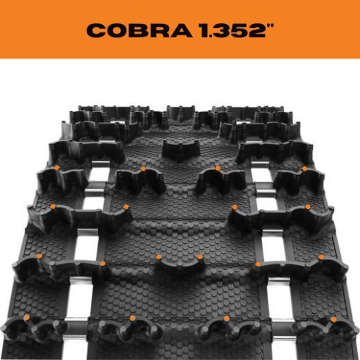 Enlarge ↗
| Model | Length | Width | Lug height | Pitch | Rows | Studs: 4–6–4 (pcs.) |
|---|---|---|---|---|---|---|
| 9052H | 121″ (3 073.4 mm) | 15″ (381 mm) | 1.352″ (34.34 mm) | 2.52″ (64.01 mm) | 48 | 224 |
| 9061H | 136″ (3 454.4 mm) | 15″ (381 mm) | 1.352″ (34.34 mm) | 2.52″ (64.01 mm) | 54 | 252 |
| 9107H | 144″ (3 657.6 mm) | 15″ (381 mm) | 1.352″ (34.34 mm) | 2.52″ (64.01 mm) | 57 | 266 |
| 9120H | 146″ (3 708.4 mm) | 15″ (381 mm) | 1.352″ (34.34 mm) | 2.86″ (72.64 mm) | 51 | 238 |
| 9235H | 129″ (3 276.6 mm) | 15″ (381 mm) | 1.352″ (34.34 mm) | 2.86″ (72.64 mm) | 45 | 210 |
| 9284H | 120″ (3 048 mm) | 15″ (381 mm) | 1.352″ (34.34 mm) | 2.86″ (72.64 mm) | 42 | 196 |
| 9307H | 137″ (3 479.8 mm) | 15″ (381 mm) | 1.352″ (34.34 mm) | 2.86″ (72.64 mm) | 48 | 224 |
Dimensions are shown in inches and millimetres.
YOUR TRACK GUIDE
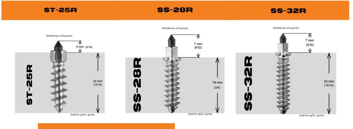
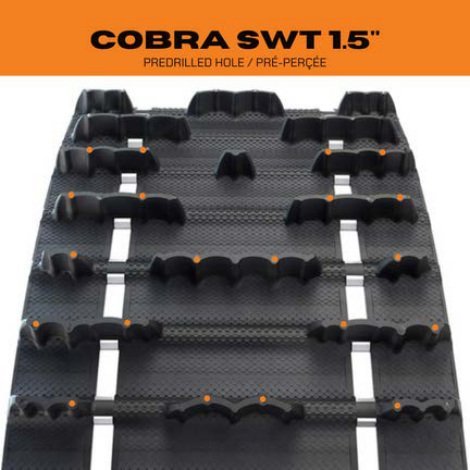
| Model | Length | Width | Lug height | Pitch | Rows | Studs (pcs.) |
|---|---|---|---|---|---|---|
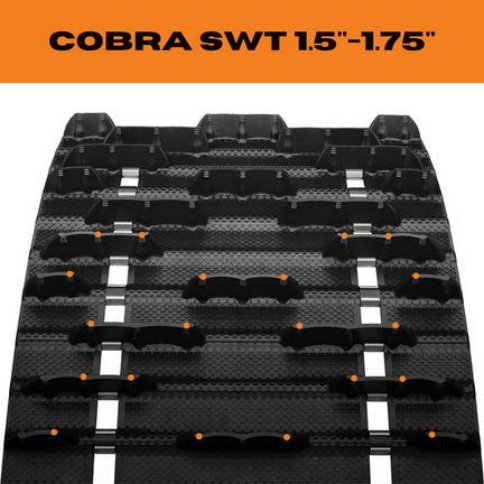
| 9422U | 154″ (3 911.6 mm) | 24″ (609.6 mm) | 1.5″ (38.1 mm) | 2.86″ (72.64 mm) | 54 | 216 |
Dimensions are shown in inches and millimetres.
YOUR TRACK GUIDE
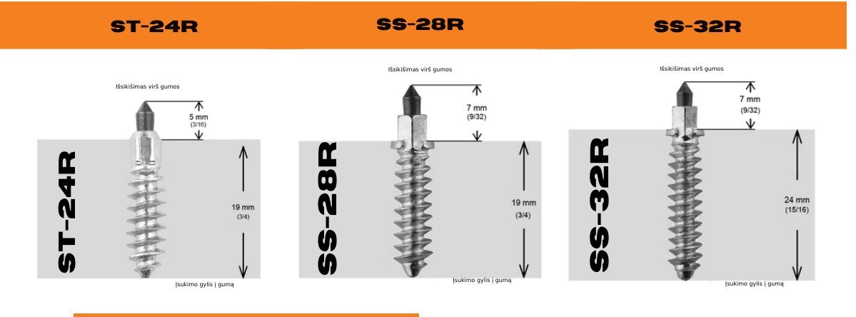
 Enlarge ↗
| Model | Length | Width | Lug height | Pitch | Rows | Studs (pcs.) |
|---|---|---|---|---|---|---|
| 9261U | 156″ (3 962.4 mm) | 24″ (609.6 mm) | 1.5″ (38.1 mm) | 2.52″ (64.01 mm) | 62 | 248 |
| 9260U | 156″ (3 962.4 mm) | 24″ (609.6 mm) | 1.75″ (44.45 mm) | 2.52″ (64.01 mm) | 62 | 248 |
Dimensions are shown in inches and millimetres.
YOUR TRACK GUIDE
| Model | Length | Width | Lug height | Pitch | Rows | Studs (pcs.) |
|---|---|---|---|---|---|---|
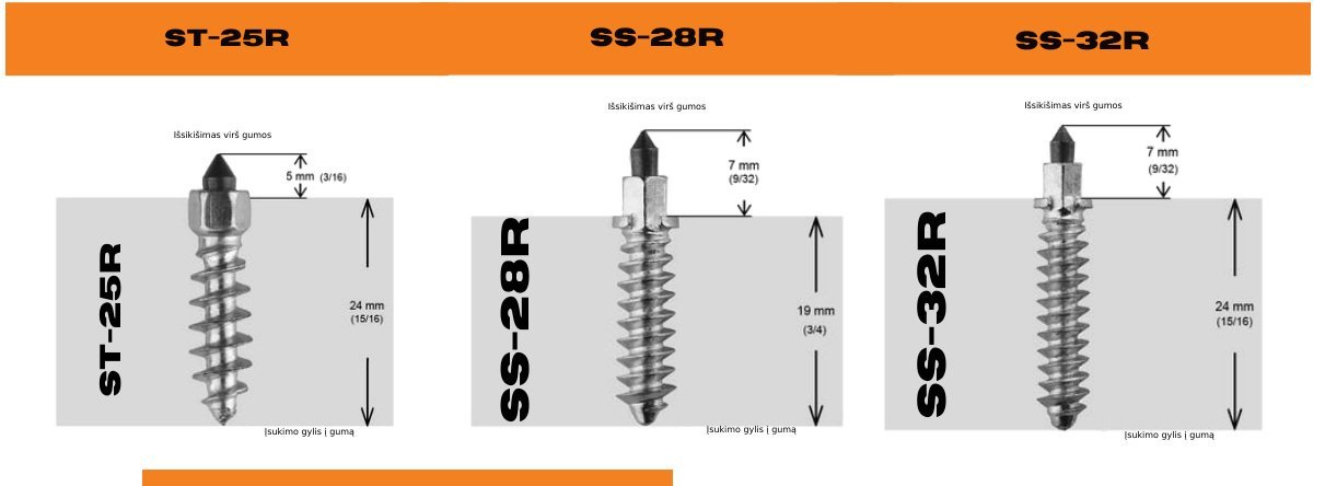
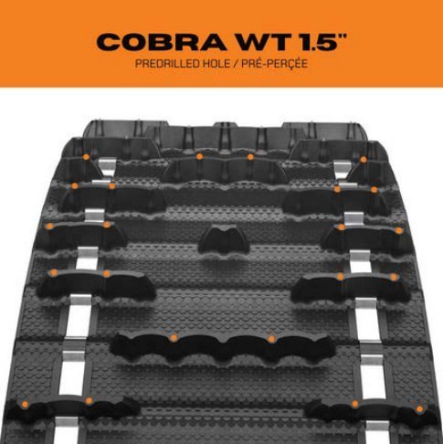
| 9366U | 154″ (3 911.6 mm) | 20″ (508 mm) | 1.5″ (38.1 mm) | 2.86″ (72.64 mm) | 54 | 198 |
| 9414U | 154″ (3 911.6 mm) | 20″ (508 mm) | 1.5″ (38.1 mm) | 2.86″ (72.64 mm) | 54 | 198 |
Dimensions are shown in inches and millimetres.
YOUR TRACK GUIDE
 Enlarge ↗
| Model | Length | Width | Lug height | Pitch | Rows | Studs (pcs.) |
|---|---|---|---|---|---|---|
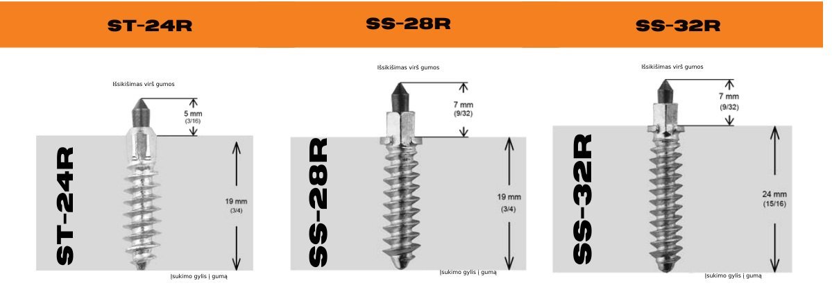
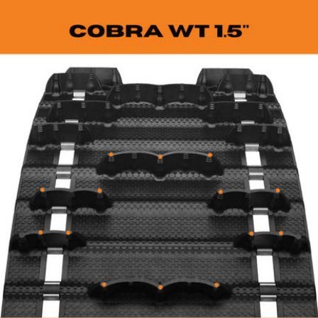
| 9196U | 154″ (3 911.6 mm) | 20″ (508 mm) | 1.5″ (38.1 mm) | 2.86″ (72.64 mm) | 54 | 198 |
| 9322U | 154″ (3 911.6 mm) | 20″ (508 mm) | 1.5″ (38.1 mm) | 2.86″ (72.64 mm) | 54 | 198 |
| 9195U | 154″ (3 911.6 mm) | 20″ (508 mm) | 1.8″ (45.72 mm) | 2.86″ (72.64 mm) | 54 | 198 |
Dimensions are shown in inches and millimetres.
YOUR TRACK GUIDE
| Model | Length | Width | Lug height | Pitch | Rows | Studs (pcs.) | Additional ST-19R (green dots), pcs. |
|---|---|---|---|---|---|---|---|
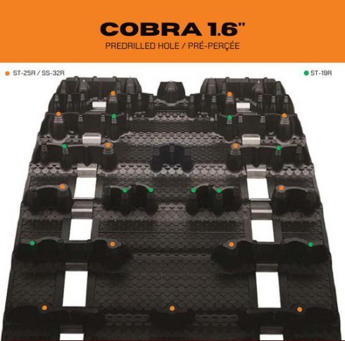
| 9244C | 120″ (3 048 mm) | 15″ (381 mm) | 1.6″ (40.64 mm) | 2.86″ (72.64 mm) | 42 | 91 | 70 |
| 9245C | 129″ (3 276.6 mm) | 15″ (381 mm) | 1.6″ (40.64 mm) | 2.86″ (72.64 mm) | 45 | 97 | 75 |
| 9246C/9264C | 137″ (3 479.8 mm) | 15″ (381 mm) | 1.6″ (40.64 mm) | 2.86″ (72.64 mm) | 48 | 104 | 80 |
| 9247C | 146″ (3 708.4 mm) | 15″ (381 mm) | 1.6″ (40.64 mm) | 2.86″ (72.64 mm) | 51 | 110 | 85 |
| 9249C | 137″ (3 479.8 mm) | 16″ (406.4 mm) | 1.6″ (40.64 mm) | 2.86″ (72.64 mm) | 48 | 104 | 80 |
| 9250C | 146″ (3 708.4 mm) | 16″ (406.4 mm) | 1.6″ (40.64 mm) | 2.86″ (72.64 mm) | 51 | 110 | 85 |
| 9272C/9282C | 154″ (3 911.6 mm) | 16″ (406.4 mm) | 1.6″ (40.64 mm) | 2.86″ (72.64 mm) | 54 | 117 | 90 |
| 9273C | 154″ (3 911.6 mm) | 15″ (381 mm) | 1.6″ (40.64 mm) | 2.86″ (72.64 mm) | 54 | 117 | 90 |
Dimensions are shown in inches and millimetres.
YOUR TRACK GUIDE
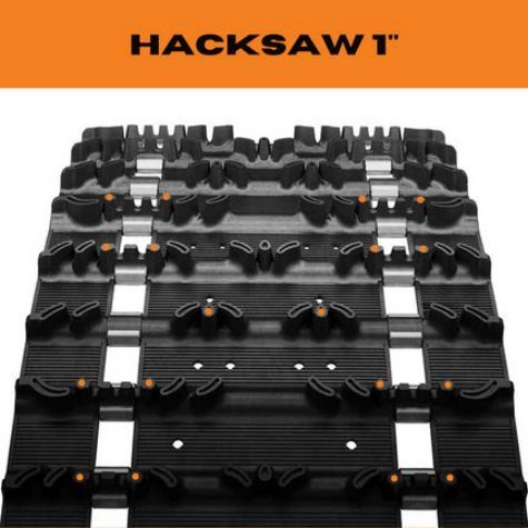 Enlarge ↗
| Model | Length | Width | Lug height | Pitch | Rows | Studs: 4–4–2 (pcs.) |
|---|---|---|---|---|---|---|
| 9010H | 136″ (3 454.4 mm) | 15″ (381 mm) | 1″ (25.4 mm) | 2.52″ (64.01 mm) | 54 | 180 |
| 9043H144 | 121″ (3 073.4 mm) | 15″ (381 mm) | 1″ (25.4 mm) | 2.52″ (64.01 mm) | 48 | 160 |
| 9110H | 128″ (3 251.2 mm) | 14″ (355.6 mm) | 1″ (25.4 mm) | 2.52″ (64.01 mm) | 51 | 170 |
| 9234H | 128″ (3 251.2 mm) | 15″ (381 mm) | 1″ (25.4 mm) | 2.52″ (64.01 mm) | 51 | 170 |
Dimensions are shown in inches and millimetres.
YOUR TRACK GUIDE
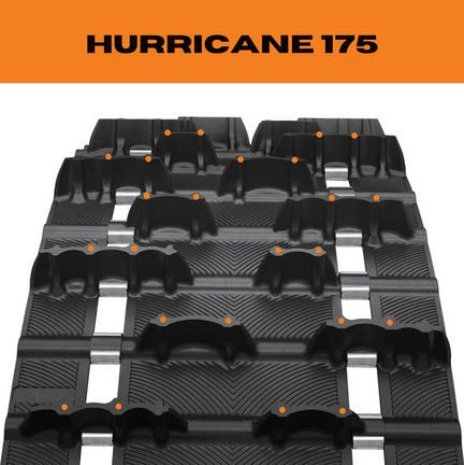 Enlarge ↗
| Model | Length | Width | Lug height | Pitch | Rows | Studs: 4–4–4 (pcs.) |
|---|---|---|---|---|---|---|
| 9400C | 120″ (3 048 mm) | 15″ (381 mm) | 1.75″ (44.45 mm) | 2.86″ (72.64 mm) | 42 | 168 |
| 9401C | 129″ (3 276.6 mm) | 15″ (381 mm) | 1.75″ (44.45 mm) | 2.86″ (72.64 mm) | 45 | 180 |
| 9402C | 137″ (3 479.8 mm) | 15″ (381 mm) | 1.75″ (44.45 mm) | 2.86″ (72.64 mm) | 48 | 192 |
| 9403C | 146″ (3 708.4 mm) | 15″ (381 mm) | 1.75″ (44.45 mm) | 2.86″ (72.64 mm) | 51 | 204 |
Dimensions are shown in inches and millimetres.
YOUR TRACK GUIDE
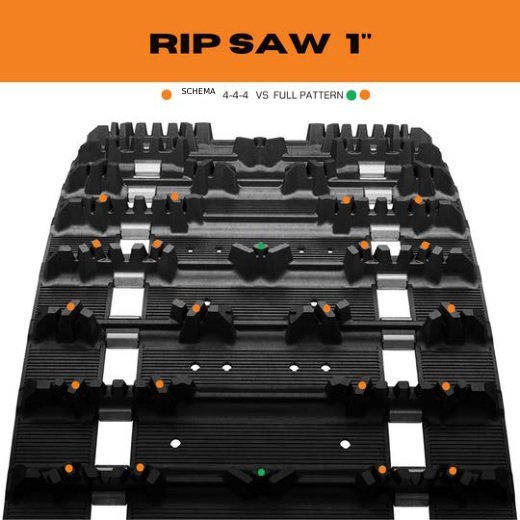
| Model | Length | Width | Lug height | Pitch | Rows | Studs: 4–4–4 (pcs.) | Studs: 4–5–4 (green dots), pcs. |
|---|---|---|---|---|---|---|---|
| 9148H | 120″ (3 048 mm) | 15″ (381 mm) | 1″ (25.4 mm) | 2.86″ (72.64 mm) | 42 | 168 | 182 |
Dimensions are shown in inches and millimetres.
YOUR TRACK GUIDE
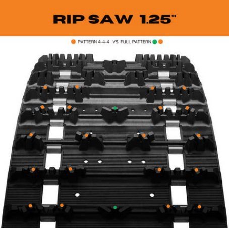
| Model | Length | Width | Lug height | Pitch | Rows | Studs: 4–4–4 (pcs.) | Studs: 4–5–4 (green dots), pcs. |
|---|---|---|---|---|---|---|---|
| 9001H | 128″ (3 251.2 mm) | 13.5″ (342.9 mm) | 1.25″ (31.75 mm) | 2.52″ (64.01 mm) | 51 | 204 | 221 |
| 9006H | 144″ (3 657.6 mm) | 15″ (381 mm) | 1.25″ (31.75 mm) | 2.52″ (64.01 mm) | 57 | 228 | 247 |
| 9007H | 151″ (3 835.4 mm) | 15″ (381 mm) | 1.25″ (31.75 mm) | 2.52″ (64.01 mm) | 60 | 240 | 260 |
| 9040H | 128″ (3 251.2 mm) | 15″ (381 mm) | 1.25″ (31.75 mm) | 2.52″ (64.01 mm) | 51 | 204 | 221 |
| 9149H | 120″ (3 048 mm) | 15″ (381 mm) | 1.25″ (31.75 mm) | 2.86″ (72.64 mm) | 42 | 168 | 182 |
| 9419H | 120″ (3 048 mm) | 15″ (381 mm) | 1.25″ (31.75 mm) | 2.86″ (72.64 mm) | 42 | 168 | 182 |
| 9968H | 121″ (3 073.4 mm) | 15″ (381 mm) | 1.25″ (31.75 mm) | 2.52″ (64.01 mm) | 48 | 192 | 208 |
| 9968H144 | 121″ (3 073.4 mm) | 15″ (381 mm) | 1.25″ (31.75 mm) | 2.52″ (64.01 mm) | 48 | 192 | 208 |
| 9969H | 136″ (3 454.4 mm) | 15″ (381 mm) | 1.25″ (31.75 mm) | 2.52″ (64.01 mm) | 54 | 216 | 234 |
Dimensions are shown in inches and millimetres.
YOUR TRACK GUIDE
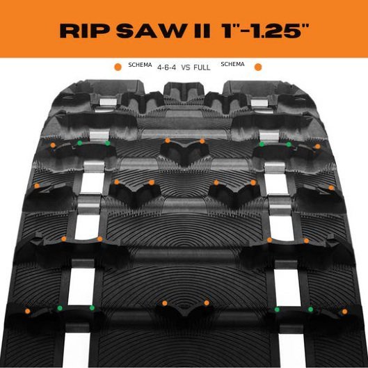
| Model | Length | Width | Lug height | Pitch | Rows | Studs: 4–6–4 (pcs.) | Studs: full pattern (green dots), pcs. |
|---|---|---|---|---|---|---|---|
| 9158H | 120″ (3 048 mm) | 15″ (381 mm) | 1″ (25.4 mm) | 2.86″ (72.64 mm) | 42 | 196 | 252 |
| 9209H | 120″ (3 048 mm) | 15″ (381 mm) | 1.25″ (31.75 mm) | 2.86″ (72.64 mm) | 42 | 196 | 252 |
| 9214H | 121″ (3 073.4 mm) | 15″ (381 mm) | 1.25″ (31.75 mm) | 2.52″ (64.01 mm) | 48 | 224 | 288 |
| 9215H | 128″ (3 251.2 mm) | 15″ (381 mm) | 1.25″ (31.75 mm) | 2.52″ (64.01 mm) | 51 | 238 | 306 |
| 9216H | 136″ (3 454.4 mm) | 15″ (381 mm) | 1.25″ (31.75 mm) | 2.52″ (64.01 mm) | 54 | 252 | 324 |
| 9223H | 137″ (3 479.8 mm) | 15″ (381 mm) | 1.25″ (31.75 mm) | 2.86″ (72.64 mm) | 48 | 224 | 288 |
| 9224H | 137″ (3 479.8 mm) | 15″ (381 mm) | 1″ (25.4 mm) | 2.86″ (72.64 mm) | 48 | 224 | 288 |
| 9237H | 129″ (3 276.6 mm) | 1.25″ (31.75 mm) | 1.25″ (31.75 mm) | 2.86″ (72.64 mm) | 45 | 210 | 270 |
| 9325H | 129″ (3 276.6 mm) | 15″ (381 mm) | 1″ (25.4 mm) | 2.86″ (72.64 mm) | 45 | 210 | 270 |
Dimensions are shown in inches and millimetres.
YOUR TRACK GUIDE
 Enlarge ↗
| Model | Length | Width | Lug height | Pitch | Rows | Studs (pcs.) |
|---|---|---|---|---|---|---|
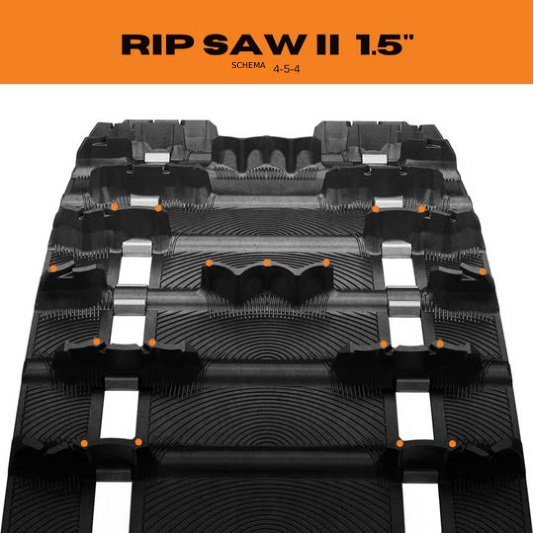
| 9304C | 120″ (3 048 mm) | 15″ (381 mm) | 1.5″ (38.1 mm) | 2.86″ (72.64 mm) | 42 | 182 |
| 9305C | 129″ (3 276.6 mm) | 15″ (381 mm) | 1.5″ (38.1 mm) | 2.86″ (72.64 mm) | 45 | 195 |
| 9306C | 137″ (3 479.8 mm) | 15″ (381 mm) | 1.5″ (38.1 mm) | 2.86″ (72.64 mm) | 48 | 208 |
Dimensions are shown in inches and millimetres.
YOUR TRACK GUIDE
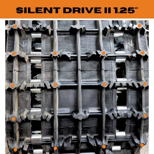 Enlarge ↗
| Model | Length | Width | Lug height | Pitch | Rows | Studs: 2–4–4 (pcs.) |
|---|---|---|---|---|---|---|
| SILENT DRIVE II | 137″ (3 479.8 mm) | 15″ (381 mm) | 1.25″ (31.75 mm) | 2.86″ (72.64 mm) | 48 | 160 |
Dimensions are shown in inches and millimetres.
YOUR TRACK GUIDE
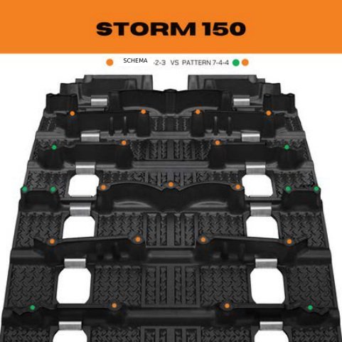
| Model | Length | Width | Lug height | Pitch | Rows | Studs: 4–2–3 (pcs.) | Studs: 7–4–4 (green dots), pcs. |
|---|---|---|---|---|---|---|---|
| 9368H | 120″ (3 048 mm) | 15″ (381 mm) | 1.5″ (38.1 mm) | 2.86″ (72.64 mm) | 42 | 126 | 210 |
| 9369H | 129″ (3 276.6 mm) | 15″ (381 mm) | 1.5″ (38.1 mm) | 2.86″ (72.64 mm) | 45 | 135 | 225 |
| 9370H | 137″ (3 479.8 mm) | 15″ (381 mm) | 1.5″ (38.1 mm) | 2.86″ (72.64 mm) | 48 | 144 | 240 |
| 9371H | 146″ (3 708.4 mm) | 15″ (381 mm) | 1.5″ (38.1 mm) | 2.86″ (72.64 mm) | 51 | 153 | 255 |
Dimensions are shown in inches and millimetres.
Drill-size reference: 3/32″ = 2.38125 mm; 1/2″ = 12.70 mm; 5/8″ = 15.875 mm; 3/4″ = 19.05 mm. Millimetre values are for comparison, not instructions to replace the iGrip drill bit with another size.
WHY IGRIP
Snowmobile track studs add grip on ice and hard-packed surfaces. A compatible stud setup can improve traction and control; the benefit depends on the surface and riding conditions.
When less power is lost to track spin on slippery surfaces, fuel use may fall. The benefit depends on the surface, snowmobile setup and riding style.
Better grip can improve acceleration and achievable speed when traction is the limiting factor, putting more power into forward motion.
A more secure hold on icy surfaces helps your snowmobile feel more stable and predictable, especially through corners.
On ice, the extra bite gives you a traction advantage over a comparable snowmobile running an unstudded track.
We believe dependable grip is one of the best investments you can make in your snowmobile — for control, confidence and performance.
Our ST and SS range offers different stud lengths and designs for different tracks. Use the finder to match the right studs to your exact variant.
02 / CHOOSE YOUR STUD
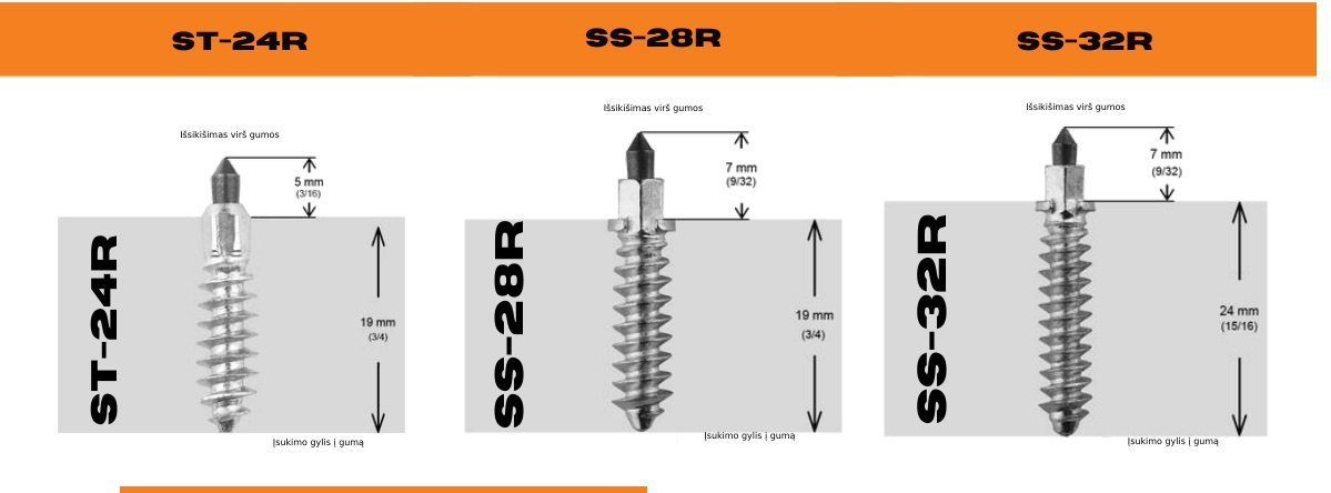
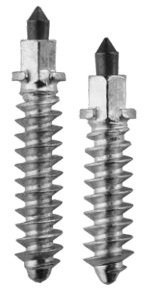
ST studs suit trail riding, corners and ice; SS studs are designed for more aggressive riding. Track compatibility comes first: follow the recommendation for your exact variant.
VERSATILE GRIP
We recommend ST studs for trails, corners and icy surfaces.
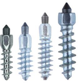
MORE AGGRESSIVE RIDING
We designed SS studs for more aggressive riding on trails and ice.
03 / PLAN YOUR QUANTITY
The number of studs depends on your track model and placement pattern. Use the quantities in your selected track table. For a repeating pattern, the calculator counts complete repetitions and any remaining rows.
Pitch is the distance between repeating track rows. Use the same units for length and pitch.
137″ ÷ 2.86″ ≈ 48 rows
3 479.8 mm ÷ 72.644 mm ≈ 48 rows.
48 rows × 4 studs = 192 studs.
For a 5–4–4 pattern: (5 + 4 + 4) ÷ 3 = 4⅓, so 48 × 4⅓ = 208 studs.
Do not round 4⅓ down to 4.3. For patterns that do not divide evenly, count complete repetitions and the remaining rows.
| Track length | Pitch 2.52″ (64.01 mm) | Pitch 2.86″ (72.64 mm) | Pitch 3.00″ (76.2 mm) | Pitch 3.50″ (88.9 mm) |
|---|---|---|---|---|
| 120″ (3 048 mm) | 42 | |||
| 121″ (3 073.4 mm) | 48 | |||
| 128″ (3 251.2 mm) | 51 | |||
| 129″ (3 276.6 mm) | 45 | |||
| 136″ (3 454.4 mm) | 54 | |||
| 137″ (3 479.8 mm) | 48 | |||
| 141″ (3 581.4 mm) | 47 | |||
| 144″ (3 657.6 mm) | 57 | |||
| 146″ (3 708.4 mm) | 51 | |||
| 151″ (3 835.4 mm) | 60 | |||
| 153″ (3 886.2 mm) | 51 | |||
| 154″ (3 911.6 mm) | 54 | |||
| 154″ (3 911.6 mm) | 44 | |||
| 156″ (3 962.4 mm) | 52 | |||
| 162″ (4 114.8 mm) | 54 | |||
| 163″ (4 140.2 mm) | 57 | |||
| 165″ (4 191 mm) | 47 | |||
| 174″ (4 419.6 mm) | 58 | |||
| 175″ (4 445 mm) | 50 |
04 / INSTALL WITH CONFIDENCE
Follow these six steps with the placement diagram for your selected track. Check pilot-hole depth, stud insertion depth and protrusion separately: they are different measurements.
Check the exact model, lug height and whether holes are already prepared.
Consider the stiffness of the track lugs and whether the pattern repeats every 3 or 6 rows.
Check their position relative to the tunnel protectors.
Do not apply one drilling depth to all tracks. For variants with prepared holes, follow their separate section.
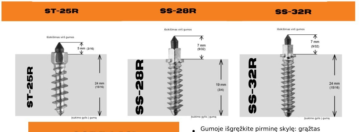
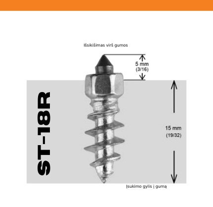
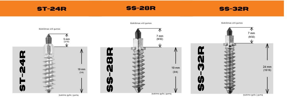
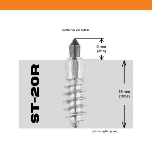
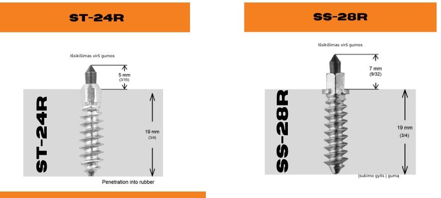
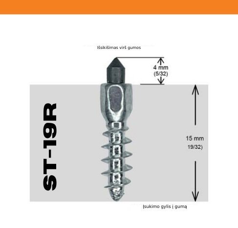
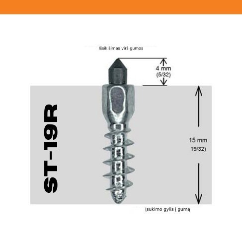
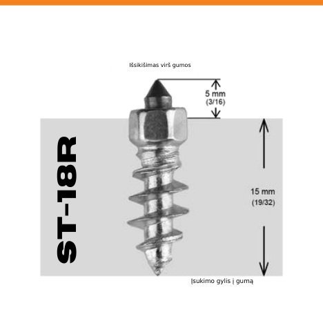
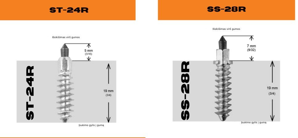
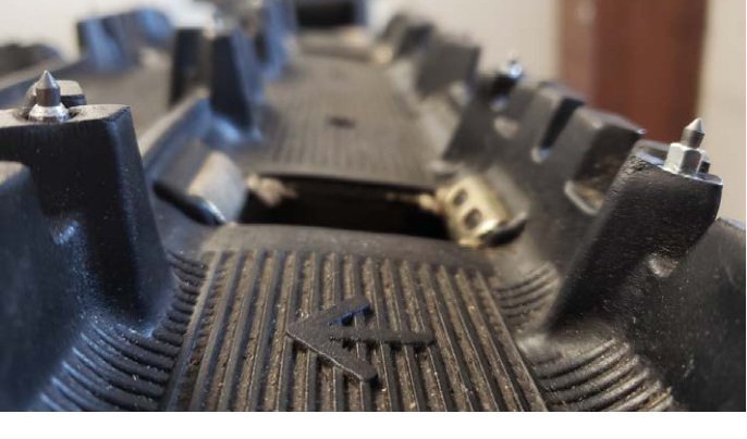
The grey area represents rubber. Distinguish stud insertion depth from protrusion above the rubber: neither is the same as the pilot-hole drilling depth.
Inspect the complete pattern and stud positions. For Ripsaw II, regularly check the insertion depth. If necessary, screw the studs in further to the position shown in the track diagram.
 Enlarge ↗
Snowmobile stud installation & maintenance YouTube ↗
05 / REAL-WORLD EXPERIENCE
See iGrip studs in use and hear a snowmobile rider’s experience. For fitting instructions, use the installation steps and the diagram for your exact track.
A RIDER’S EXPERIENCE
Properly installed iGrip studs can last for the entire lifespan of your snowmobile. They are durable, highly resistant to wear and remain firmly secured in the track.
Hear from one of our customers, a passionate snowmobile enthusiast.
QUICK ANSWERS
Not every track needs drilling. Some variants have factory-prepared holes. Select the exact variant in the track finder and follow its drilling instructions. Cobra 1.6″ has separate drilling dimensions for additional ST-19R studs.
The meaning depends on the track. On Cobra 1.6″, green dots identify additional ST-19R studs. Other track tables use green dots for an alternative or full pattern. Read the quantity column labels before combining or comparing stud counts.
Drilling depth is the depth of the pilot hole. Insertion depth is the length of the stud inside the rubber. Protrusion is the part above the rubber. These measurements are not interchangeable: follow both the drilling specification and the stud illustration for your selected track.
NEED A HAND?
Do not select a pattern just because a track name looks similar. Send us the details and we’ll help you identify the right setup.
Ask iGrip for help ↗